
6 - Electronics Design
Intro
The assignment of this week was to learn how to design an electronic circuit modifying the Hello Board adding a led and a button.
Modifying the HelloBoard
To design or modify a circuit you need a CAD software designed to do this. I started installing Eagle for Mac. It is a CAD software made for design circuits. I looked around for a simulator because I wanted a tool to test my circuits before milling but I wasn't able to find a simulator for Eagle neither a Spice version working on mac. So I discovered the 123D Circuits simulator and played with it a little bit but it is not a professional tool and doesn't have all the features that Eagle has. I also installed and played a little bit with Fritzing ad I saw that there are many open source projects sharing Fritzing design.
An electric circuit is and ensamble of electronic components linked in a certain way. However there are a lot of components and a lot of version of every single component (depending on manufacturere, charachteristics etc). For this reason you can add libraries to Eagle I installed a library on Eagle (from here) with the components in the inventory of the Fablab and I started modifyng the circuit. Eagle open two windows: the schematic and the board. The schematic is the abstract view of the circuit useful to decide how to link the component together. The board is the view of the components on the board.
I started from the scheme, trying to figure out what components are needed. To use the button and the led there is the need also to add two resistors to the circuit to prevent the led to burn and the button to cause a short-circuit. As the led, according to its datasheet, requires 2V and 25 mA to operate I used the Ohm's Law to calculate the correct value of the resistor to apply. The board is powered with 5v so the voltage drop should be 3V. Ohm's Law says thet R=V/I so the value of the resistance is equal to 3/0,025= 120 Ohm however the nearest commercial value is 150 Ohm. For the resistor to be applyed to the button I chose a 10Kohm pull-down resistor to avoid a short circuit when pressing the button. I decided to connect a pull-down resistor so I can read a LOW value when the button is not pressed and an HIGH value when it is pressed.
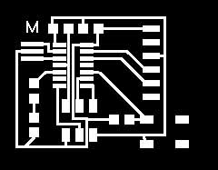
Then I switched to the board view. I drawn the traces between the new components. Eagle has an auto-route function however I did it manually. The fun part was to find enough space to place the components on the board changing the precious routing. I used the space underneath the button to let a trace pass without having to enlarge the board. To mill my board I selected only the Top and the Pad layers. I exported the image setting the resolution @600 dpi. With GIMP I created also another file to cut the boundaries of the board. I used the fabmodules to create the gcode files for the Roland. I decided to add an "M" on the board to make it more personal :)
The original board:

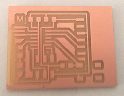
The modified one:
Then I milled the board with the Roland SRM-20. I followed the procedure explained in the Electronic Production assignment.
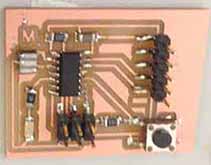
I also soldered the components (the hardest part was the microcontroller) and I made a continuity test with the multimeter.
Debugging
During the assignment 7, despite the initial cointinuity test was good, I discovered that there was some short circuit on the board. So I designed another version with more spaces between the traces under the microcontroller. Have a look at the assignment 7 page for more details. On the githum repo you can find also the old files while in the download section I linked the last version.
Download
 Attribution, non-commercial, share alike.